Unexpected SLS behaviour or warnings such as “Large nodal displacement” and “Equilibrium error”?
This article explains how “Same for all calculations” works when editing multiple objects in FEM-Design, why the checkbox may appear blank or become unchecked, and how this can lead to unexpected differences between calculation types.
Typical symptoms include larger deformations in SLS than expected, behaviour that differs between ULS and SLS, or warnings such as Equilibrium error and Large nodal displacement or rotation found. In some cases, unintended differences between calculation types can contribute to those symptoms.
In most cases, this behaviour is expected. It reflects FEM-Design’s flexible and protective handling of grouped edits when selected objects do not have identical settings in all calculations.
Quick overview: Symptoms, cause, solution
Symptom: The checkbox may appear blank or become unchecked after grouped edits. Cause: The selected objects do not have identical settings in all calculations. Solution: Decide whether the change should apply only to the active calculation or to all calculations, then re-enable the option if needed.
Typical situation
A typical case is that two supports, connections, or similar objects differ between calculation types, for example in stiffness, even though “Same for all calculations” was originally enabled.
When you select both objects at once and change a parameter for both objects, FEM-Design may automatically turn the option off and apply the change only to the active calculation.
Why this happens
1. Change only the active calculation (e.g. ULS)
If the change is applied only to the active calculation, the other calculation types keep their existing settings.
2. Change all calculations for all objects
If the change is applied to all calculations, the selected objects receive the same properties in all load cases and combinations.
What FEM-Design does
To avoid overwriting those differences unintentionally, FEM-Design disables “Same for all calculations” when grouped edits are made to objects that are not identical in all calculations. This protects existing per-calculation settings and gives the user more control when different behaviour is intended.
In practice, this means the edit is applied only to the current calculation, while existing differences between calculation types are preserved.
Why the checkbox becomes blank
When several objects are selected, a checked box means they share the same state, an unchecked box means the option is disabled for all of them, and a blank box means the selection is mixed.
Even if the option is enabled for all selected objects, they may still behave differently because their per-calculation properties are not identical.
A blank state therefore means the selected objects are in a mixed state rather than fully identical.
What to do in practice
Quick checklist
- After editing multiple objects, decide whether the change should apply only to the current calculation or to all calculations.
- If the objects should behave the same in all load cases and combinations, re-enable “Same for all calculations”.
- If results look unexpected, compare the object settings across calculation types.
Examples
Example 1: Why are deformations much larger in SLS?
A model may look reasonable in the default ULS view, while the same supports or connections have different properties in SLS. In that situation, load distribution and deformation behaviour can change significantly even though nothing obvious appears to be wrong at first glance.
A typical case is that stiffness has unintentionally been changed only for one calculation type after editing multiple objects. The user then notices unusually large deformations in SLS, even though the behaviour in ULS still looks normal. Checking whether “Same for all calculations” is enabled for the affected objects is often the quickest way to confirm the cause.
Example 2: Why do I get “Large nodal displacement or rotation found”?
This issue is often not discovered through visible differences between ULS and SLS, but through computational warnings. A support, edge connection, or similar restraint may have lost its intended stiffness in one calculation type while still appearing correct in the default view.
In that case, FEM-Design may report warnings such as “Computational warning messages”, “Fatal error: The equation system is unsolvable. The stiffness matrix is singular.”, “Equilibrium error” or “Large nodal displacement or rotation found”. The underlying cause can be that the model is properly restrained in one calculation type but under-restrained in another. If this is the main symptom, compare the settings across calculation types and also review the related troubleshooting article for large displacements and rotations.
Recommendation
As a general rule, keep “Same for all calculations” checked. FEM-Design supports both consistent everyday modelling and intentional calculation-specific differences, but in most workflows the safest and clearest choice is to keep the checkbox checked unless you deliberately want different properties in different calculations.
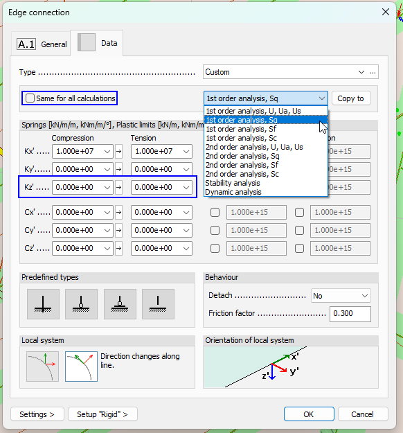
Figure. Example where stiffness Kz' is inadvertently set to zero in all calculation types except the first selected analysis, “1st order analysis, U, Ua, Us”, which can lead to very different behaviour between calculation types.