There are a few features that are not so commonly known, one of which is the Profiled plate and the usage of trapezoidal steel sheet. In the following guide we will explain the usage of profiled plates to enhance the design of lightweight roofs.


The feature of profiled panels is located in the Structure-tab in 3D Structure.

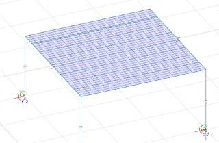
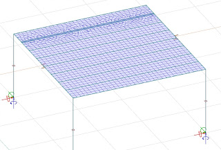
This example shows a simple structure and how to add the trapezoidal steel sheet as a roof.

First we need to add the profile to the section library. Do this by the Section Editor-module, it can be found under Tools > Section Editor.

Draw the contours or use an external reference to add the background lines, then use Draw Section to generate the profile. The following image shows a profile generated in Section Editor.

Next step is to calculate the profile, and add it to the Section library.


Start the Profiled plate command, and select Default settings. There are a few settings that need to be explained:

Physical model: Selection of cast in-situ or prefabricated elements. Prefabricated elements enable possibility to set panel edge connection properties.
Panel type identifier: For the program internal numbering of elements. Recommendation: leave as default.
Gap between panels: This is not an actual gap. It is more like a filler-space to get the panels to have a width that is better divided with an even number. Concrete hollow-core elements are usually 1197 mm and a 3 mm gap makes the objects in FEM-Design 1200 mm. It basically gives the physical space in the panels in the real world a stiffness so that the 1197 mm panels aren't stacked exactly next to each other. As for this steel sheet (width = 735 mm) I have added another 15 mm to make the FEM-Design object 750 mm and to make it evenly distributable over a 6 m wide area (8 elements instead of 8.163265...). It will be possible to work with divided elements as well, so if I had a width of 6500 mm I could still use 735+15 and get 8 elements and one cut element that is one third of a real element (250 mm in this case).
Analytical model: Used for prefabricated physical model to select a continuous plate or panel-by-panel type.
Transverse flexural stiffness factor: Different stiffness parameters in different directions. E1 is the actual stiffness of the material in the main direction, while E2 is the stiffness in the weak direction. If E2/E1 is 0.1 then the structure will only have one tenth of the stiffness in the weak direction and thus transfer 10% of the load in that direction while about 90% will go in the stiff E1-direction. Basically the same as Orthotropy for plates but this is only in flexural direction (displacement out of plane).
Alignment: This setting will not affect the calculations, only the presentation. See the first picture of this page for reference.
Eccentricity: This option will change the stiffness by adding the eccentricity*area-term to the original stiffness value if the checkbox for 'Consider eccentricity in calculation' is ticked.
Border tab:
These are the boundary conditions of the whole slab towards the surrounding objects (beams, walls, etc.).
Panels tab:
The settings in this tab are the boundary conditions between each of the panels. If they are not connected in the vertical direction to each other, but want them to transfer forces in the horizontal plane, then set Kz' to zero. This would simulate a hollow-core floor without grouting, or a thin steel sheeting without a rivet-connection. In the finished structure a connection between these objects are usually common practice so in that case, use the Hinged button to connect the panels internally with a hinge connection.

When all settings of the slab has been set, press OK to return to the model. Now we need to define the direction of the slabs, this is done by choosing two points in the direction of the slab. This step is quite important that it will be completely straight. If it is not then the program might create very thin slabs due to the direction of the slab is not the same as the direction of the slab-edge.

Next step is to define the borders of the slab, often a polygon shape is needed, but a rectangle works for most occasions.


Finished geometry:

Loads:
When applying a load as 'Pick existing region', each panel is a region. To add a load over the whole slab, use 'Polygon'- or 'Rectangle'-tools.

The setting of the mesh with 'Region by region'/'Consider all regions together' might create very different meshes and thus have very different calculation times. The result should not be affected that much though. If Cast in-situ or Prefabricated/continuous options are selected the slab will be modelled as similar as a normal plate, but with stiffnesses like the section selected.
(consider all regions together)
(Region by region)
This difference is important to know since connecting slabs might cause meshing problems in the line between the regions. If the regions are not thoughtfully considered then these meshing issues might spread over to walls.
