When designing steel structures a few of the beams or columns might be supported for lateral torsional or shear buckling. Instead of defining point supports in those points that might cause the model to act as if totally supported, beams and columns can have their buckling length defined as if supported by reducing the buckling length. Here we will explain how and where to set the buckling lengths.

The structure in this example consists of steel columns, beams and a thin steel sheet (modelled with profiled panels) as a stabilizing slab. The loads on the structure are lineloads distributed over the horisontal beams and as a surface load on the thin steel sheet.

Now go to the Steel design tab and make a design calculation. Click on the word ’Analysis’ and select the Accurate elements, this is a more advanced finite element type that will generate more accurate results.
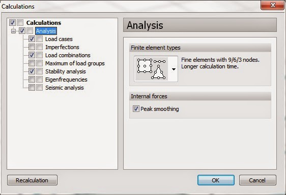
Do not be scared by the text ’Longer calculation time.’ For this model it is a matter of seconds and the recommendation is to allways calculate with it unless the result is not needed to be exact.
Select the stability analysis aswell to see if the structure is stable, this usually helps to see if something is missing or has been modelled wrong aswell (= critical parameter is close to zero).

Three buckling shapes are often enough, it is the 1st that will be the one happening in reality and the 2nd and 3rd are just mathematical results and can be considered as ’If the first doesn’t happen, then the second one will occur, etc.’
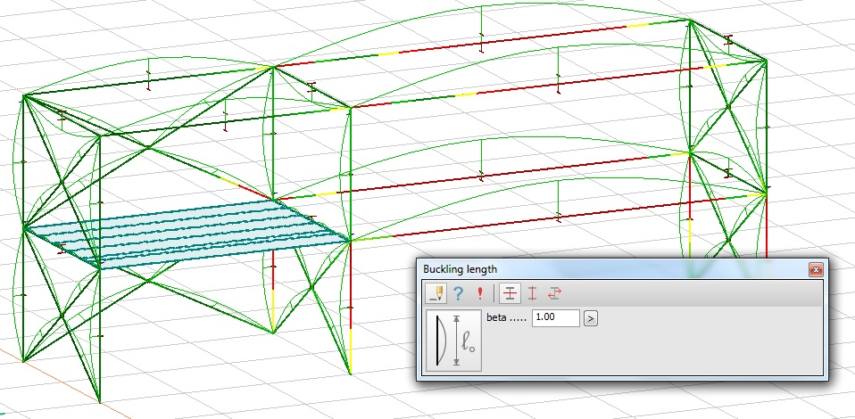
Make the calculation and then select the result ’Steel bar utilization’

As can be seen many of the beams have a utilization above 100% (shown as red).
The magnifying glass has also been highlighted in the toolbar.

Click on it and then on a beam with more than 100% utilization.
This beam is actually braced in the roof and we want to set the buckling length to 5m instead of 10m. Go back to the model by clicking on the Model 1.-tab below the calculations (similar to Excel).
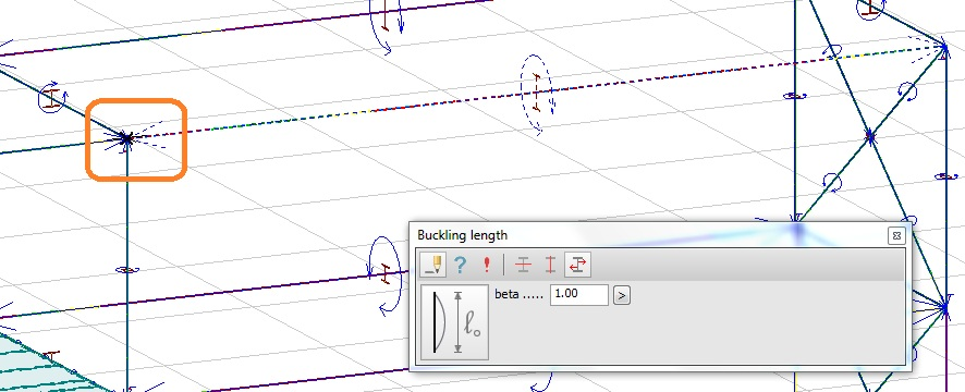
Now we will brace the beam by reducing the buckling length. Click on the buckling length icon.

The toolbox for the buckling parameters will appear. There are three options for buckling, flexuaral buckling in strong and weak directions and then the last option lateral torsional and shear buckling.
Parameters for buckling in strong direction:
Parameters for buckling in weak direction:

Parameters for lateral torsional and shear buckling:
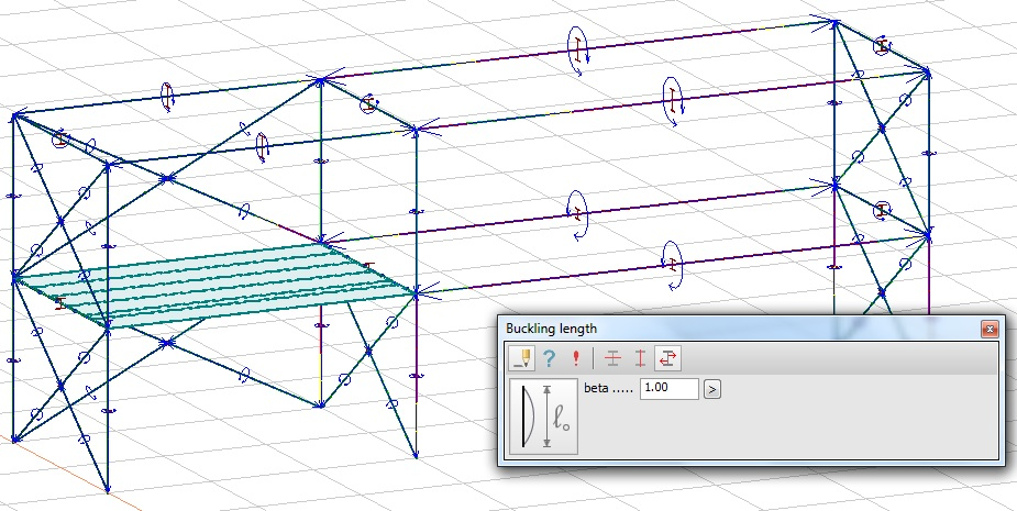
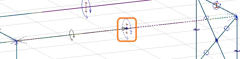
Now, right-click on a bar and set the buckling length with start point. A black x will mark the start point:
…and then set the end point:
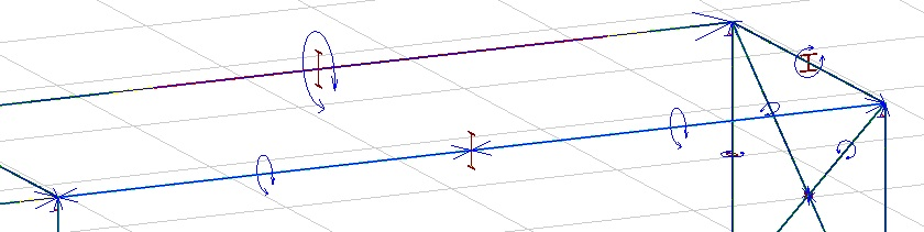
Finished result:
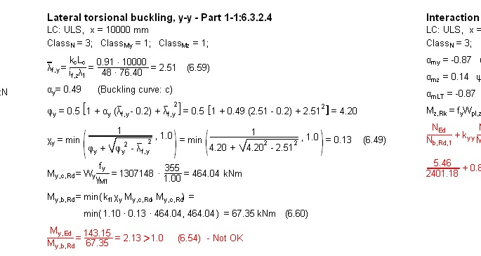
Now check the bar with the new settings:
Right click on the bar and use the magnifying glass to see the detailed result:

Beam are now OK for lateral torsional buckling!